
The concept of a sub kick is very simple, take a large speaker and use it in reverse as a microphone specifically for picking up low frequency information, from a kick drum for instance. This can be used in the mix to reinforce the sound of the kick alongside another kick drum mic, providing additional depth to the sound due to it’s focus on the sub 100Hz frequency range. The subkick won’t pick up much spill from other parts of the kit either, and a good trick is to use it to trigger a gate on the internal kick drum mic, to get a very tight and clean kick sound.
Various companies make them, the Yamaha SKRM100 for example, which is essentially a 6.5″ woofer mounted in a small drum shell, with mesh either side and a built in stand. The price, £350, quite a bit for speaker on a stand! Over the years I’ve seen various DIY versions in studios around the way including an NS10 woofer clamped into an old worktop vice as a base, all these incarnations functioned well, and cost significantly less than £350 to make. Time to get the tools out I thought.
This is an easy DIY project, it involves mounting a woofer speaker into a suitable frame (in this case a tambourine shell), and then a little soldering to attach an attenuator and a male XLR connector.
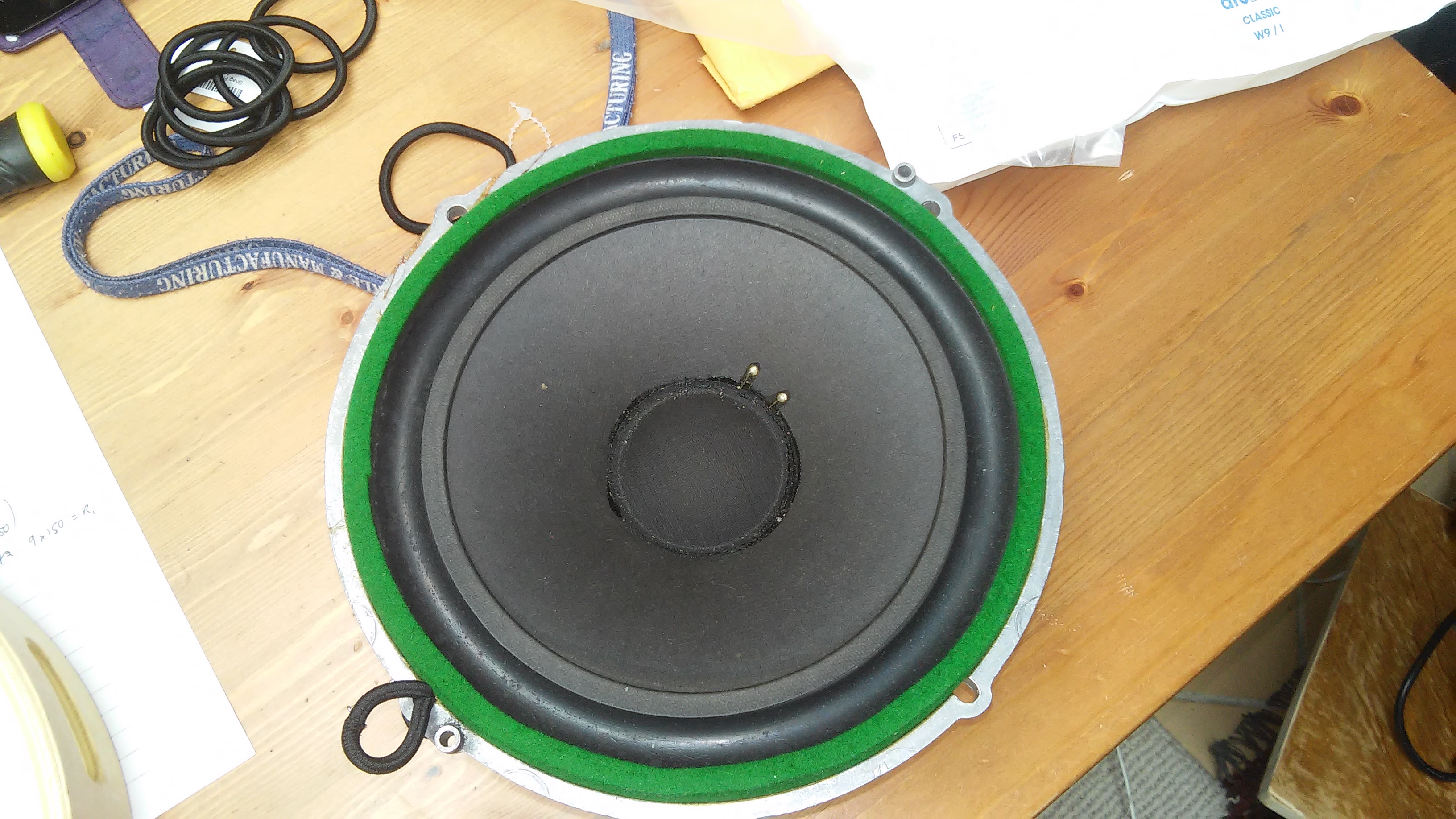
First start with a speaker, I went for an 8″ Wharfedale woofer of EBAY (approx £18), you can use anything from 6″ up, though some say it doesn’t work as well with larger speakers. I’m not sure about that, the 8″ seems to work pretty well. Most important is the speakers frequency response, it should go down to about 20Hz to get all those sub bass frequencies.
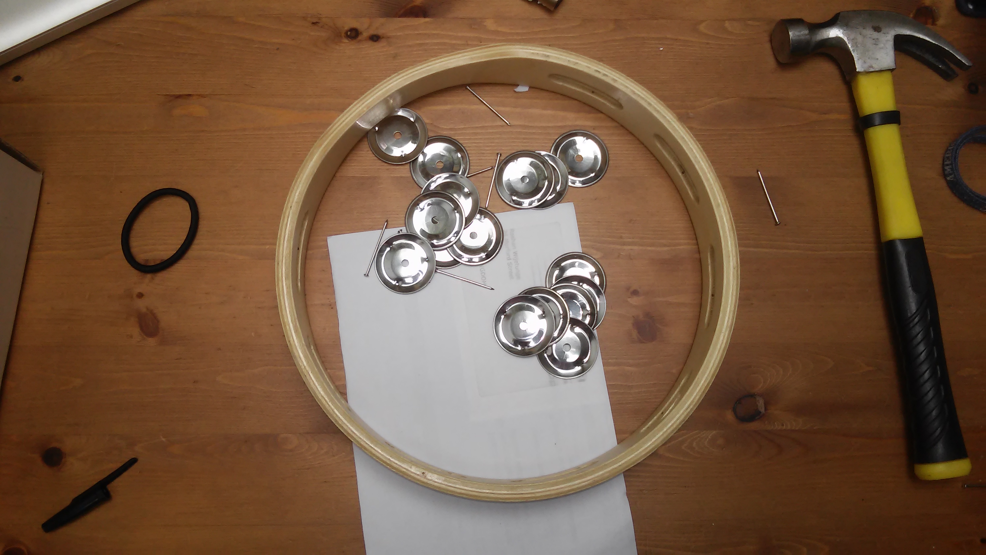
I thought a lot about how to mount it, I wanted something that would isolate it and look good, but not cost too much. The cheapest and most elegant solution I could think of was to use elastic hairbands to suspend the speaker within the circular frame of a tambourine (without the jingles of course). So I ordered a 10″ tambourine (£7 Ebay) and removed the jingles by pulling out the nails holding them in place.

Slip the elastic hairbands through the screw holes in the speaker, then feed each end through one of the slots in the tambourine rim and push the upper loop (the one that goes over the rim) round and under so the 2 loop ends overlap. Take the nail that used to hold the jingles in place, push it back through it’s location hole so that it pegs the 2 loop ends of the elastic in place. Push all the way in so it’s secure. That was probably the trickiest step in all of this, required a lot of patience to get the elastic and the nail to all go in the right place. Repeat this for the remaining screw holes.

The next challenge was figuring out how to mount the the subkick using a normal mic stand. I happened to have a broken mic stand lying around so I took the pivot mount from it (the bit that screws onto the top of the vertical part of the stand and allows the boom to attach to it and swivel up and down). The advantage of using this was that it had a standard screw thread on the end which meant I could attach it to a regular mic stand (as shown in the picture above). The pivot mount itself attached to the tambourine rim with a nut, bolt and a couple of washers (through one of the existing slots in the tambourine).
Next step is connecting it up to a mic pre-amp. The output of the subkick is pretty hot, an attenuator (or pad) is recommended to bring the signal level down to the region expected by most pre-amps. You can buy an inline attenuator that connects between the subkick and the XLR cable to the pre-amp, or you can knock together a basic potential divider circuit to do the job for you. I opted for the latter as you probably guessed. Another point worth mentioning here is that I’m going to use an unbalanced connection, providing the environment isn’t to (electrically) noisy and cable runs are short, this shouldn’t be an issue. If you wanted to go for a balanced connection, you would need to wire in an audio transformer, and to get one that has good sub-sonic frequency response isn’t going to be cheap. You could also use a DI box, again, a good quality one with good bass response would be preferable.

The schematic for an attenuator circuit is shown above, I used a simple potential divider, the values I chose for the resistors R1 and R2 are:
R1=680 Ohm , R2 =150 Ohm
There are many combinations you could use and they also depend on your speaker, Google “attenuator for Subkick” if you want to get lost in that world!
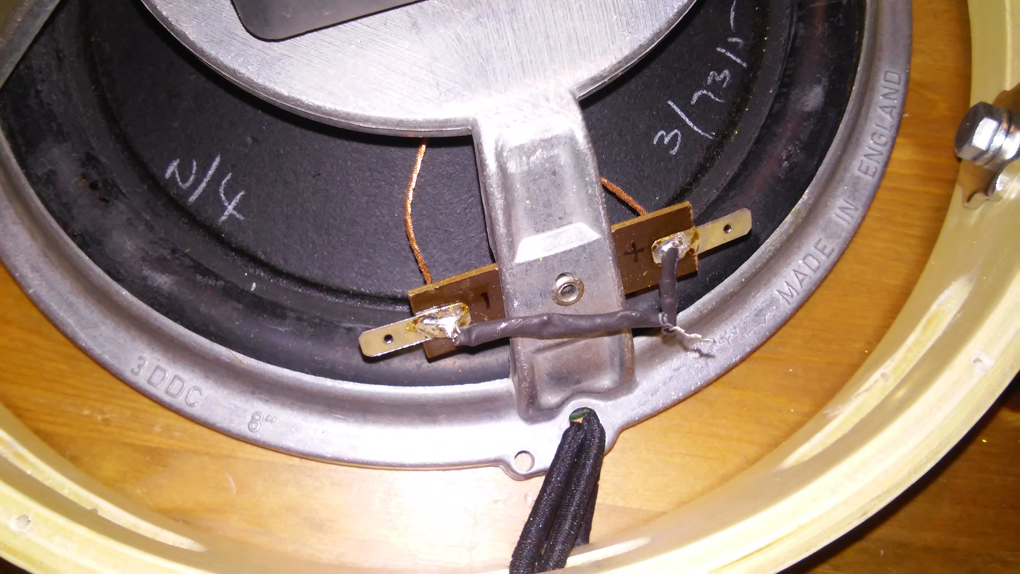
With the resistor values chosen, I soldered them directly to the speaker terminals and covered them with heat shrink. Easiest way I found was to solder one end of R2 to the speaker – terminal, and one end of R1 to the speaker + terminal, slide a sheath of heat shrink over each resistor then twist the exposed ends together, before applying heat to shrink the insulation (see above).
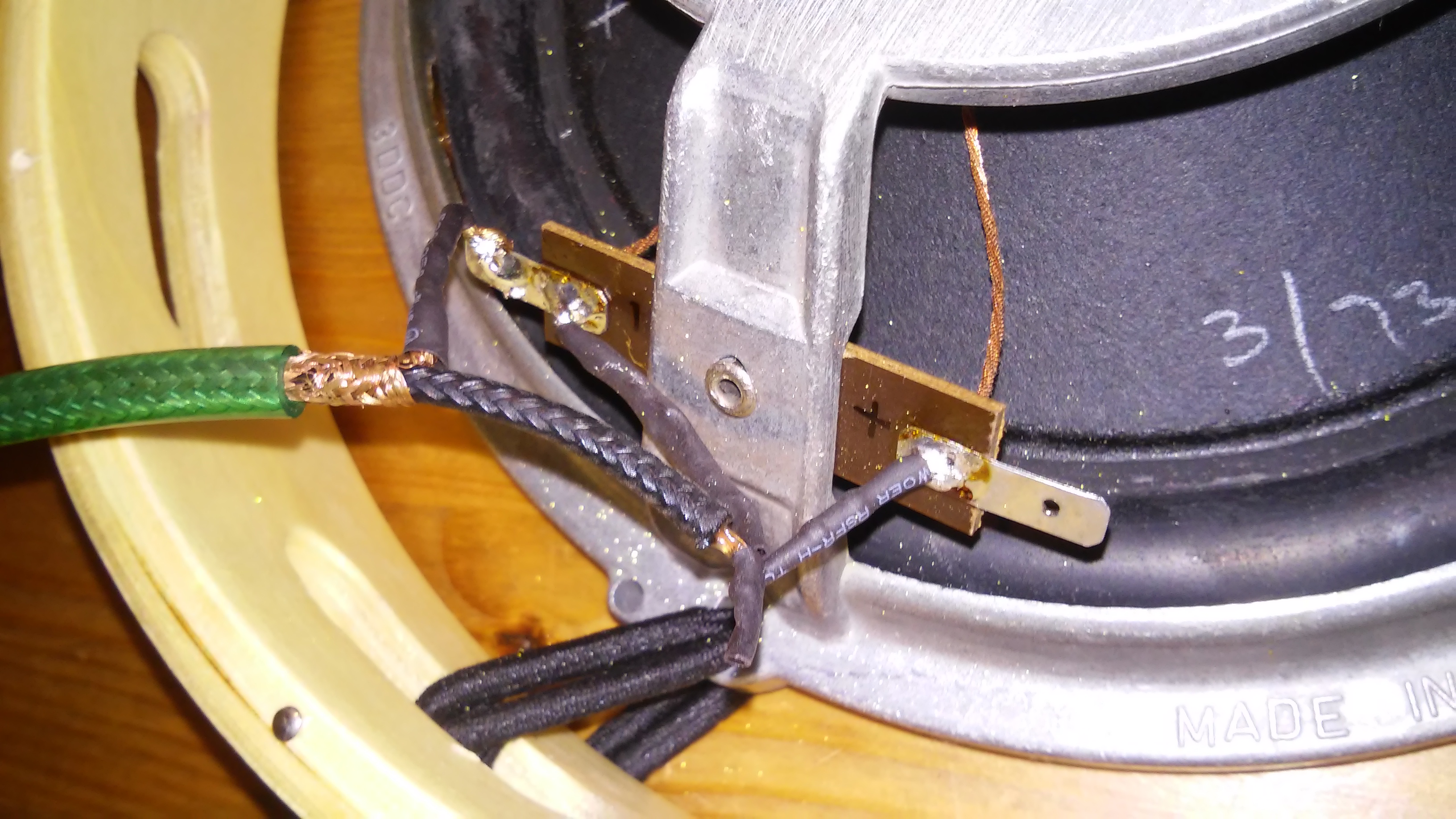
I then soldered a short length of guitar cable to the speaker – terminal and the exposed resistor ends, ensuring I had a sleeve of heat shrink in place to insulate the connection.

Finally I soldered the male XLR connector onto the end of the cable, (Pin 1 to Speaker -, Pin 3 to the resistors, Pin 2 unconnected). I had a retaining clip lying around so I used that to secure the connector to the frame, so as not to put too much mechanical load on the soldered joints.
So there you have it, a fully functioning subkick that doesn’t cost an arm and a leg, doesn’t look to shabby, and is not to difficult.

Here is a quick audio example of the subkick in action. The audio is as follows
Bars 1-2 : Internal kick mic only
Bars 3-4 : Subkick only
Bars 5-6 : Internal mic + Subkick
Bars 7-8 : Internal mic + Subkick (with gate on subkick)
Bars 9-10 : Full kit, no subkick
Bars 11 – end : Full kit with Subkick

The sub Kick reasonates at a definite frequency which you could do without.
It is true that the sub-kick will have a resonant frequency, all speakers do have one, but the extent of the resonance varies from speaker to speaker. A guitar cabinet speaker for example tends to be over-damped and thus displays less resonance than a hi-fi woofer. The overall idea is to capture low frequency content that would not be so well reproduced by more standard microphones, you can then EQ and process the dynamics of that signal to acheive the sound in teh mix you require.