
There comes a point when many a recording engineer starts to consider the finer points of the recording chain, and inevitably finds themselves in the esoteric world of mic preamps. These days there are so many choices both off the shelf and DIY, so many opinions, and so many fuzzy descriptions of ‘warmth’, ‘open-ness’, ‘transparency’ etc…It’s hard to know where to begin.
I began by accident. I bought a job lot of electronic components off EBay, the seller claimed that all the components required to make a Neve preamp were included. Well, that was optimistic, I think there were about 4 capacitors and a handful of resistors that could be used, but anyway it piqued my interest. I found out the project board he was intending to use which led me to the fabulous www.groupdiy.com website, where Martin Adriaanse has created a complete guide to building the EZ1290 Neve preamp clone, including a bill of materials, circuit schematics, build guide and some basic troubleshooting points. You can purchase the PCBs directly from him (they are not available anywhere else).
My first decision was whether to go the complete DIY route (where you have to source all the parts yourself) or go for one of the many kits provided by the likes of Seventh Circle Audio or JLM Audio . Being the masochist that I am, I opted for buying the PCBs and sourcing components myself using mainly Mouser in the UK, how hard could it be? Of course, some of those nice polystyrene capacitors weren’t available on Mouser, nor were the BC184 transistors and a few other little things, so I ended up on EBay where I found pretty much everything else I needed.
The Neve sound is all about transformers, and not just any old ones; properly designed, carefully manufactured transformers made for the specific task of interfacing microphones and line level signals. You need 2 per channel, an input mic transformer and an output line transformer. These aren’t cheap, I got mine from Audio Maintenance Limited who also sell the Grayhill rotary switches used for the gain selector. All in, 2 channels worth of xformers and switches cost the best part of £200 once delivery was factored in.
Once the components were in, soldering the PCBs was a relatively straightforward task, pay attention to put things in the right place and use a heatsink on those capacitors. Use a fine tip soldering iron (especially for that rotary switch, the pins are tiny and close together) and audio grade solder.
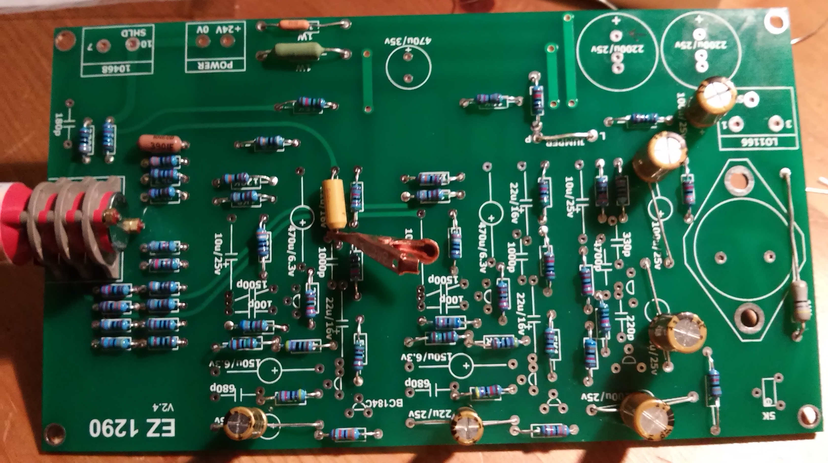
I started with resistors first, then smaller caps, then transistors and larger caps.

Note the overkill polystyrene capacitor on the right, couldn’t find the right voltage spec one for that capacitance so had to go for a 400V spec, hence the size. Still fits and works!
Building the boards was the easy bit to be honest. Once they were done the fun of trying to fit everything into a case and route the wiring began. I got a 1U rack case off EBay again, it was from a network router so needed a bit of tidying up, and I also ordered a plain aluminium front panel which I was going to attach on top of the existing front plate. I’ll admit that the rack case was probably my biggest cock-up. I thought it was full depth but when it arrived it was a shallow one, so stuffing all the PCBs, transformers and connectors in was going to be a challenge.

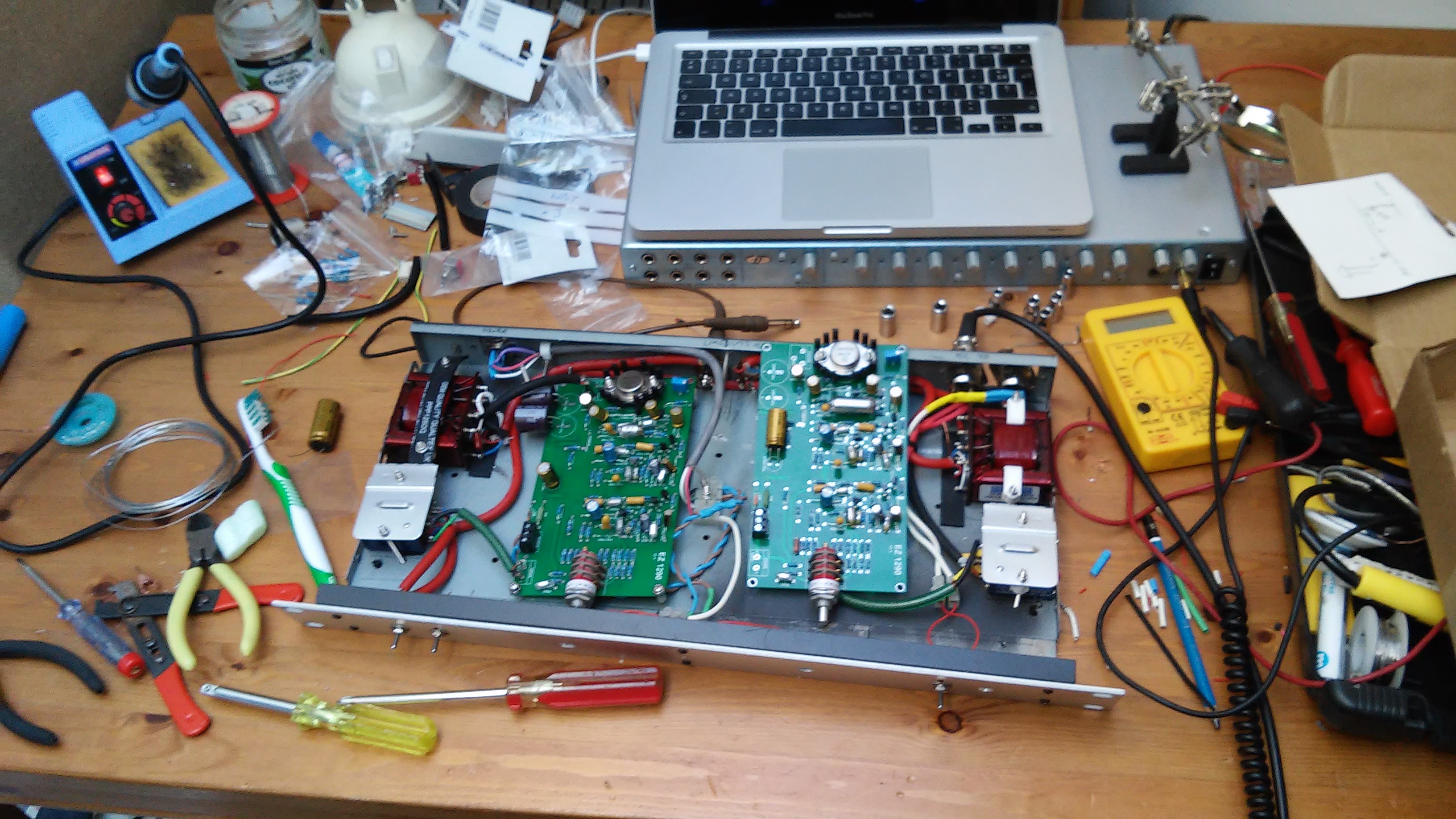
I put the transformers for each channel down the sides and the PCBs in the middle. This just about worked, I had to leave space for input, output and power supply sockets too.
I wanted to make use of the input transformers multi-taps, so I could make a switchable impedance for the mic inputs. Although not strictly necessary these days as most mics are designed to work with the typical high impedance of most mic preamps, it can help when interfacing with older mics and it also offers another tonal option for a given mic. The taps on the primary side of the transformer allow the two halves of the primary to be wired in series (1200Ω) or parallel (300Ω), I wired in a switch to change the configuration via the front panel.

The only other switch I fitted was a +48V phantom power switch. Phantom power is introduced to the hot and cold connectors on the input XLR via 6.81K resistors. I left out phase and pad switches for now. I also opted not to fit the output trimmer. You ideally need to use a high quality pot, I think I may add this for the next build as it allows you to drive the input stages harder for more grit if you want it. Some people say that the trimmer degrades the sound quality slightly, that’s a better reason than not being arsed to fit it.
The other important piece of the puzzle is the power supply. These boards need a +24V supply as well as +48V for phantom. I had no choice but to locate all of this in a separate enclosure, though with careful planning you could fit all this into a larger rack unit (watch out for induced mains hum from the power supply transformer). JLM do a suitable power supply, I already had a toroidal transformer so found a PSU kit from a Russian supplier on EBay. These do the job, but I blew the first one with an accidental short circuit.
Once everything is connected, you need to bias the output transistor, for this you ideally need an oscilloscope and a signal generator. I used a 1kHz test tone from my sound card and a borrowed scope from the local university, very useful diagnostic tool and I might have to invest in one if I’m going to do this more often. Biasing is explained in the build guide and is a pretty straightforward procedure, just adjust the trimpot till you get symmetrical clipping and your done. Pushing it too far in the wrong direction can make things get very hot.
My first board wouldn’t bias properly, I ended up swapping all the transistors in the output driver stage and it all worked ok after that, took a bit of head scratching though, the build guide gives a few tips such as the typical DC voltages at each of the transistor pins but it wasn’t obvious which was the culprit.
I had some intermittent hum issues, I was using the case as a ground so I implemented a star grounding scheme, seems to have worked.
I used a powder coated metal enclosure for the power supply, this is a pain as the individual panels don’t necessarily conduct with each other so the safety ground had to be wired to each panel to ensure proper earthing.
I blew the 1W resistors on the + side of the board supply rails by letting the underside of the board accidentally touch the case (which is earthed) when testing, won’t be doing that again.

So here is the finished version. Sure, it’s a little chaotic and Heath Robinson in there, I used whatever material I had to hand to make things like cable guides and mountings for the transformers. But this is my first build.
I’m glad I chose to do it this way, you learn so much more by going through the stages yourself, figuring out details like how to package and connect up the system and then troubleshooting it, making mistakes, blowing components, ordering the wrong thing etc….I know what to do next time. Speaking of which, I’m considering this project as a prototype; I’m planning to get another 2 boards and build a 4 channel unit into a 2U (full depth) case, and add pad and phase switching for each channel, and maybe a switched mode power supply instead of that bulky and noisy toroidal transformer.
All in all it has been a lot of work (and expense) to get these mic-pres up and running, however, they work beautifully and I’ve been getting some great results on guitars, vocals and drums. I’m even starting to use words like ‘warm’, ‘open-sounding’ and ‘big’ when I describe the recordings. In the next post I will put up some examples to illustrate why I think they are worth the effort.

2 thoughts on “The DIY preamp saga”