
Modifying the T.Bone SC1100 Large Diaphragm Condensor Mic

I bought one of these mics a while ago on the recommendation of a vocalist friend. Considering it cost about £100 from Thomann it was a good deal; 3 patterns, transformer coupled and smooth-sounding with none of the top end harshness of other mics in this price bracket. It also came with a nice metal case and decent shockmount. However, it is still flawed, there is a distinct scooped sound to it which can be flattering but also leads to lack of clarity, and the low frequency response is muddy or ‘woofy’, which is probably a lot to do with transient response.
I did some research to see if anyone had performed a mod on it, but very little came up, until I came across a this thread on the Advanced Audio Europe forum:
“…The SC1100 has a discrete class “A” transformer coupled circuit based on the original AKG 414 from the early 70’s. This circuit has 14db more headroom than a U87.
The capacitors in the SC1100 are already high quality tantalum and polypropylene. R10 can be changed to a 2.2K which will increase the output level and headroom by 3db.
The SC1100 has a dc to dc converter board similar to the U87AI in order to polarize the rear diaphragm via the pattern switch with 110 v dc for FIG 8.
The SC1100 has a low tech single winding transformer that works remarkably well when driven from the much lower output impedance of the 414 circuit.
We can supply a 2.25:1 transformer with dual bobbin windings and bi-metal laminations for $59. Our 2.25:1 transformer will take 6db more level than the stock transformer and recover much faster from percussive transients.
The SC1100 has no pre-emphasis and there is lots of room in the head grill for either our AK47 or AK67 which will both work well with that circuit.
The AK47 will give it a more U47fet tone but with 3 patterns and the AK67 will give it a more U87 tone but with more headroom….”
Looks like someone else had the same idea, I contacted Advanced Audio and they supplied me with a new capsule (AK67), transformer and resistor to perform a relatively simple upgrade to this mic.
The result? A clearer, more precise mic with nice tight bass response. You can opt for a different capsule of course, and this will change the character of the mic, they recommend their AK47 or AK67 capsules. I found the AK67 added back the mids that seemed scooped in the original, giving a lot more presence to recorded sources, I’ve included some quick audio examples at the bottom of this post.
The basic cost of this mod was 145 Euros plus p&p for the AK67 capsule BV2.25 transformer, and they very kindly threw in the 2.2k resistor as well.
If you’re interested in performing this mod yourself, then I will outline the procedure I followed. I would say this is an easy to medium mod, you will need to be confident with soldering and desoldering components (see here for some good tutorials), and not be squeamish about completely dismantling the microphone!
Disclaimer: Be aware that you could damage your mic if you get this wrong! I am in no way responsible for any damage that may occur as a result of following my guide. Use common sense and take care and you should be fine, if in doubt or lacking confidence, find someone who can help!
You will need:
- Suitable replacement capsule , transformer and resistor (many suppliers can provide these components, I found Advanced Audio Europe to be very helpful in recommending the right parts, get in touch with them here)
- A temperature controlled soldering iron with a fine tip
- Desoldering pump
- Audio quality solder (4% silver)
- 1mm dia. heat shrink
- wire cutters / strippers
- Set of small Phillips screwdrivers
- 99.9% Isopropyl Alcohol, a toothbrush and / or cotton buds (for cleaning the solder joints afterwards)
- (optional) A crocodile clip to use as a heat sink when soldering near heat sensitive components.
- (optional) A camera
Time required is about 1-3 hours depending on how skilled you are (took me about 3 and I’m not that skilled!)
1) Prepare your workspace
Not essential but this is how I like to work: have a clear, clean workspace with good lighting ready, warm up the soldering iron and lay your tools out. I grounded myself for ESD protection, not sure if it’s strictly necessary but I did it anyway, I have a wire connected to the radiator pipe which I wrap round my finger.
I took photos every step of the way so I could refer back to see where wires were connected or how things fitted together, very useful and no hassle these days with camera phones.
2) Dismantle the mic
– Unscrew the base of the microphone, slide off the body sleeve and put both parts to one side.

-With an appropriate screwdriver, undo the 2 screws either side of the head basket and then remove the basket and he plastic locating ring that mounts the headbasket to the inner metal runners.

– I’m not sure if it’s strictly necessary, but I found it easier to completely dismantle the mic to work on it, so I removed the 4 screws on each PCB that hold them to the frame, and the 6 screws holding the transformer case and XLR connector to the frame too.


– desolder from the PCBs the 3 wires coming from the capsule. I found it better to do this than cut them as the blue wire on the replacement capsule was not quite long enough so I had to exchange it for the one from the original capsule. (Use a heat sink on the leg of the capacitor to prevent damage when desoldering). If necessary, ensure you take a picture(s) of where the wires connect so there is no confusion when reconnecting.


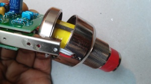
3) Remove the existing transformer
– As you’ve seen, the transformer is located in the metal can at the bottom of the mic, open this and pull the transformer out, it is usually stuck to the lid with an adhesive pad.
– cut the wires to the transformer fairly close to the transformer itself, the replacement has short wires and you will need to splice them to the existing wires in order to reach the PCB.

4) Install the new transformer
-The replacement BV2.25 transformer is dimensionally quite different, you will need to install it lying on its side in order for it to fit in the can. I wrapped the metal core of mine in electrical tape, not sure if it’s necessary but the original was wrapped up too so I figured it might be useful to do. Route the wires through the 2 entry holes on either side of the transformer can.


– Prepare the ends of each sets of wires for soldering (strip and tin where necessary), place a sheath of heat shrink on the long wires leading to the PCB and push down out of the way.

– match up the colours of the wires from transformer to PCB and solder them together, you may need some clamps to hold the wires in place as you do this.
– slide the heat shrink sheaths over the joins and apply heat till they contract, ensure no bare wire is exposed.

– relocate the wires in the metal runners and assemble the transformer can and XLR connector back into the frame. Replace the 6 screws taking care not to pinch any wiring in the metal runners.

5) Swap the resistor
– Locate the resistor labelled R10 on one of the PCBs, flip over and locate the solder joints corresponding to this component.

– using the desoldering pump, desolder and remove the resistor (I will assume you know how to do this, but if not sure then here is a good guide: http://www.tangentsoft.net/elec/movies/)
– fit the replacement resistor, solder and trim the terminals
6) Capsule swap
– If your not intending to re-use the existing capsule, then you don’t have to be so careful about handling it. With the new capsule, only hold if from the sides and don’t pull on the wires connecting to the front and rear faces of the capsule.
– remove the existing capsule from the plastic saddle by removing the 2 holding screws either side
-Take the new capsule from it’s case and locate it on the saddle so that mounting holes are aligned with those on the saddle. Using the screws provided with the capsule, screw the new capsule in place and tighten, ensuring there is no play.
– feed the capsule wiring through the holes in the top plate of the microphone leading to the PCBs. If the blue wire appears to be too short, then you can remove the blue wire from the old capsule by undoing the retaining screw and swap it with the wire on the new capsule.
– to avoid accidental damage to the exposed capsule, I slipped the metal sheath from the mic body over the capsule, this is particularly usefull when it comes to soldering the wires onto the PCB as any spurts of solder could potentially damage the diaphragm

– resolder the capsule connections, the blue wire goes to the shared terminal with the capacitor (use a heat sink to protect the capacitor), and the red wires go to the terminals on top of the other PCB. To avoid confusion, the PCB with the 3 way pattern select switch is mounted on the front side of the mic, the wire from the front side of the capsule goes to the right hand side connection when looking at the back of the PCB.

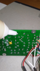
– clean the back of the PCB and all new solder connections with the isopropyl alcohol
7) Re-assemble and Test
– re-attach the PCBs using the screws, be aware of the capsule and avoid damaging it, replace the plastic ring and headbasket, now you can relax a bit as the capsule is protected! slide on the body sheath and tighten the base, the black backing plates to the pattern select and filter switches are likely to have come off and will need inserting before you put the body back on.

– plug it to your preamp, apply phantom power and test, speak into it first and make sure you are getting signal, then try it on a range of instruments or vocals and see how you like it.
Good luck, I hope you enjoyed and / or have found this useful, I’ve made 2 of these mics now and am very happy with the recordings I’m getting from them. Here are some quick audio examples to illustrate the change in character of the modified mic compared to the standard version:

Great guide Tosh, I’m inspired. I might see if any of my mics could be improved with a bit of geeking…
Thanks Benji, glad you enjoyed it. Go on, embrace your inner geek…
Great job! But i think that you have replaced a capsule with an identical one! The sc1100 altready use a k67 35mm (ak67) capsule. Am I wrong?
Hi, yes, you are correct, but I’ve replaced it with a higher quality capsule. Although they are the same type, the difference is pretty big.
Just a word to thank you for your excellent tutorial. I have modified my own SC1100 with a K47 capsule and I think it now sounds really great. Anyway, you’ve been a big help to understand how to improve a very good little mic. 😉
Hi, I’m glad you found it useful, they are good mics and worth the effort of upgrading, I use mine alongside more usual choices such as AKG c414 and they definitely hold their own.
Great tutorial, nice clear photos. I’ve just bought an SC 1100 but there is no indication in the tech docs of the frequency ‘rolled off’ using the low-cut switch. Do you have any idea of the frequency (75/80/100 Hz?) and the roll off curve? I know that ears provide judgement on whether the roll off is good or not but I do like geek details! Thanks for any help.
Brilliant! Very nice detailed and clear tutorial. thank you very much. I own a SC 1100 as well, and like the appeal of it, it really makes a great optical impression and sounds quite decent for the price. Mine sounds a little harsh in the high mids though, maybe what you call scooped. What iI could hear from your sound samples (they are MP3, right?) is a more round accentuated bass and more clarity in the mids, I’m just wondering if I should go with a RK87 or 67 capsule. I already own a Audio Technica AT 4050/CM which is said to sound near to a U87, so maybe the 67 would give me a nice alternative. I certainly want to keep the multipattern functionality…
I’m pretty sure the RK87 capsule has isolated backplates and thus 4 wires instead of the 3 found with the RK67, so you’d need to look into that. The RK67 is the type of capsule used in U67 / U87a from what I can gather, but clearly it’s more than just the capsule that makes a mic sound the way it does. Good luck experimenting, ultimately it’s up to your ears!…
It isn’t true C414 circuit, it has much more poor input topology and other parts of the circuit are definately worse “re-designed”. There’s no single polypropylene capacitor inside, all are chinese polyester capacitors, and there are used two poor quality tantalum capacitors which should be replaced with better grade aluminium electrolytic. Also there’s no 110V from dc converter, since it use negative voltage to create fig.8 pattern. This voltage converter is a little bit waste of its potential. It only delivers ca. 54V and -54V which is not much difference than usual ca. 47V in the circuits without it. Strongly reccomend to rise the voltage around +/-63-65V.
Changing transformer from stock chinese 2:1 to rebranded chinese with similar ratio doesn’t change much except waste of money. Stock transformers are pretty linear in whole bandwitch. Rather also i wouldn’t swap k67 to another k67, here definately K47 or K12 (read all the chinese edge terminated k67 like advanced audio version) fit much better.
Most nasty bug in this circuit are oversized RF filtration capacitors which comonnly chinese manufacturers are using to “smooth” k67 response. Remove C1 and C2 (if you have no problem with radio frequency in your environement) or change them to 1nF-4.7nF range. Then you will hear much more real response of the cpasule without distortions in HF range.
Happy digging 😉
Thanks for your input, it’s always good to get differing opinions on these things. I went with advice I was given at the time and am happy with the results I have achieved, though one thing that I would like to change is to add a pad or increase headroom so they can be more useful on drums.
So how would I go about raising the voltage to +- 63-65V?
Hello Roshan, thanks for the mod guide! I would like to use the SC-1100 for bass drum reso micing. Do you think the 125dB SPL would be sufficient or will it start clipping? Did you follow your idea to add a pad to the mic? Thanks, Moritz
Thank you for the detailed tutorial! The mod did make a very nice improvement to the sound. 🙂 Have to consider upgrading my SC1100 aswell.